DESIGN BASICS
BULK 3D PRINTING
design basics
Wall thickness
Wall thickness is one of the most important aspects in 3D printing design. It refers to the thickness of the walls of a 3D object and has a direct impact on the strength, durability, and final appearance of the printed model.
How Wall Thickness Affects the Final Result
Strength and Durability:
- Appropriate Thickness: An appropriate wall thickness provides the necessary strength for the object to withstand mechanical forces and stress. A wall that is too thin can make the object fragile and prone to breaking.
- Excessive Thickness: Excessive thickness can result in a heavier object and may consume more material, increasing the cost and print time.
Print Quality:
- Thin Walls: Very thin walls can be difficult to print correctly and may show defects such as warping or adhesion failures. In high-resolution prints, thin walls may not form well and might be invisible in some models.
- Thick Walls: While thick walls tend to be more stable and durable, they can affect the precision of fine details in the design.
Print Time and Costs:
- Material Efficiency: Thinner walls use less material and can reduce print time and cost. However, this must be balanced with the need for strength and durability.
Tips for Optimal Wall Thickness
Consult Material Recommendations:
- Each type of printing material has a recommended range for wall thickness. For example, for filaments like PLA, a wall thickness of 1.5 to 3 mm is usually suitable for most applications.
Minimum Recommended Wall Thickness in FDM:
- Recommended: 1.0 mm to 1.5 mm
- Minimum: 0.8 mm
Consider the Object’s Final Use:
- Decorative Items: For decorative pieces that do not need to bear For decorative pieces that do not need to bear , you can opt for thinner walls to save material and time.
- Functional Items: For pieces that need to withstand stress or For pieces that need to withstand stress or , increase the wall thickness to ensure strength and durability.
Test and Adjust Thickness:
- Perform test prints to evaluate how different wall thicknesses affect the object’s quality and functionality. Adjust the thickness as needed to balance quality, strength, and cost.
Optimize the Design:
- Use design techniques such as internal reinforcements or support structures to reduce the need for excessive wall thickness without compromising the object’s strength.
Use Appropriate Slicing Software:
- Use slicing software that allows you to visualize and adjust wall thickness before starting the print. This helps identify potential issues and make design adjustments.
Check Printer Settings:
- Ensure that the printer is properly calibrated and that settings such as fill density and print speeds are optimized for the selected wall thickness.
Surface quality and print orientation
Surface Quality
Surface quality in 3D printing refers to the texture and visible finish of the printed object’s surface. This quality can vary depending on several factors, including printer resolution, the material used, and print settings.
Factors Affecting Surface Quality:
Layer Resolution:
- Thin Layers: Printing with thinner layers (e.g., 0.1 mm) tends to produce a smoother and more detailed surface. Thinner layers reduce the visibility of layer lines, improving the finish.
- Thick Layers: Thicker layers (e.g., 0.2 mm) can speed up printing but may result in a rougher and less detailed surface.
Material:
- Materials like PLA and PETG: Typically offer a smoother and shinier surface finish.
- Materials like ABS: May require post-processing, such as sanding or polishing, to improve surface quality due to their tendency to form visible striations.
Print Orientation
Print orientation refers to the position of the object on the print bed. The way an object is oriented can significantly influence the quality and strength of the final piece.
Impact of Orientation:
Strength and Durability:
- Z-Axis (Vertical): Orienting the object with layers along the Z-axis generally offers more resistance to forces acting in the horizontal direction (X/Y), but can result in a less uniform surface.
- X/Y-Axis (Horizontal): Printing the object along the X or Y axis can provide a more uniform surface but may reduce resistance to vertical forces.
Surface Finish:
- Visible Surface: Orienting the object so that visible surfaces (outer faces) are aligned with the X or Y axis can help improve the quality of the visible surface.
- Supports and Fillers: Orientation can minimize the need for support structures, which can affect surface quality and require additional post-processing.
Fragile Points and Vertices
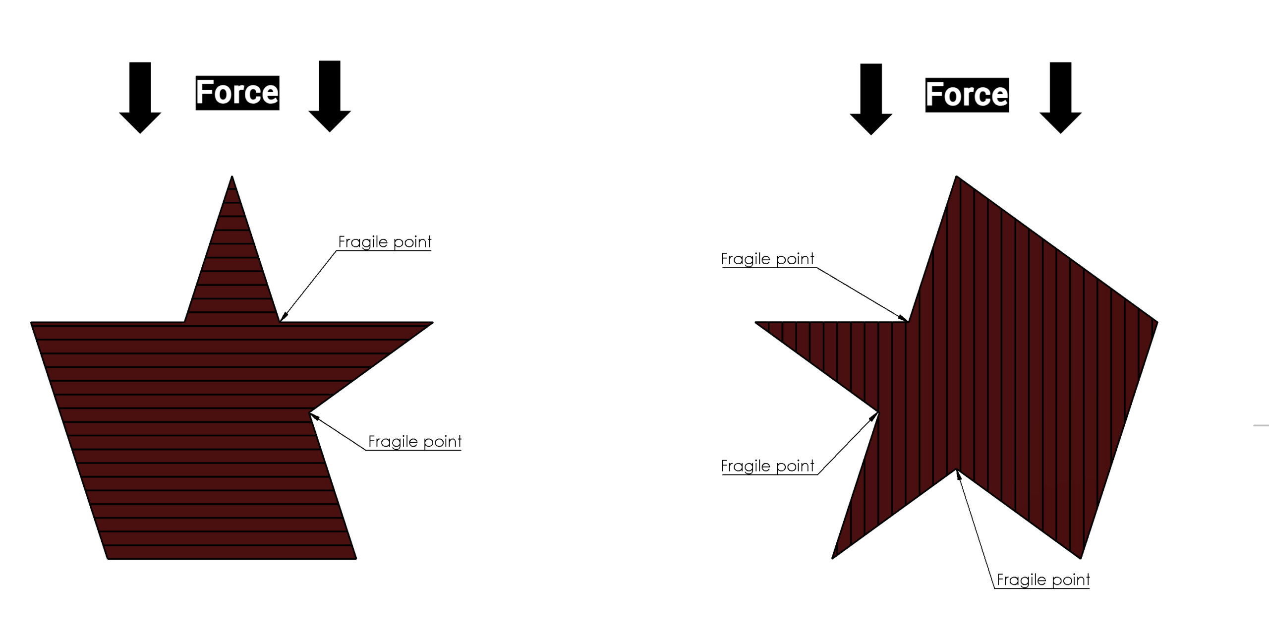
In 3D printing, fragile points and vertices refer to areas of a model that may be more susceptible to failure or breakage due to their geometry or the way they are printed. These vulnerable spots can impact the strength and durability of the final object.
Impact of Fragile Points and Vertices on the Final Result
Structural Strength:
- Stress Points: Sharp vertices or points where multiple Sharp vertices or points where multiple surfaces meet can concentrate stress, making them more prone to fractures or deformations.
- Thin Areas: Very thin areas or sharp angles can be especially weak and prone to breaking under pressure or impact.
Durability:
- Wear and Damage: Fragile points and vertices may wear out quickly or get damaged with regular use, reducing the lifespan of the object.
- Assembly Failures: In assembled parts, weak vertices can affect the accuracy of the assembly and overall functionality.
Aesthetic Quality:
- Deformations: Fragile points can deform or collapse during the printing process, affecting the finish and appearance of the object.
- Visibility of Defects: These points may become more evident after post-processing, such as sanding or painting.
Model Accuracy and Tolerances
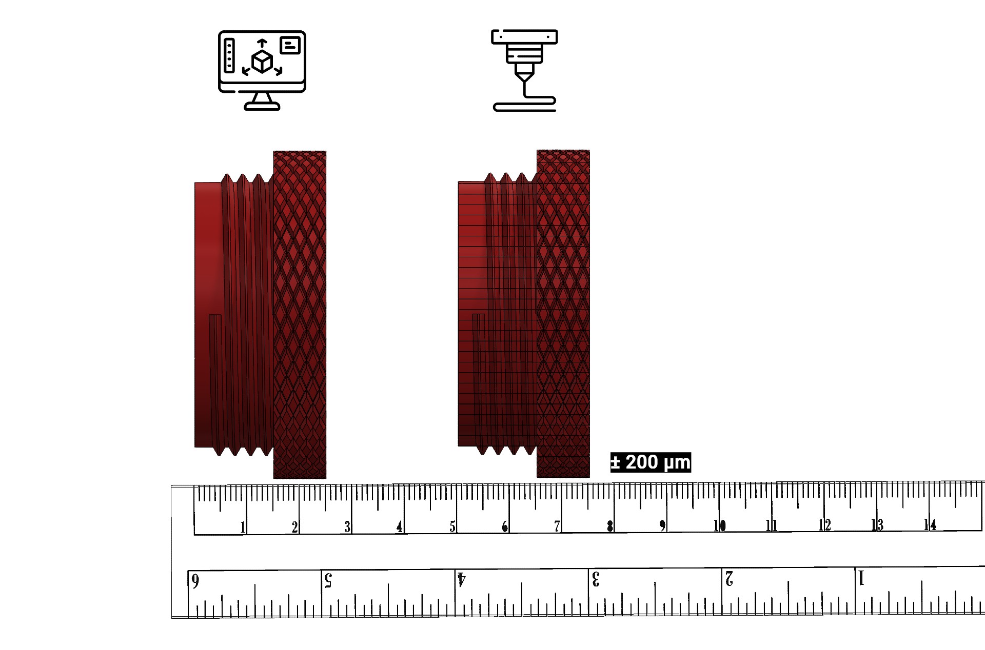
In 3D printing, model accuracy refers to the ability of the printing process to reproduce the design accurately. Tolerances are the allowed variations between the dimensions of the digital model and the printed object. Understanding and controlling these tolerances is crucial for achieving precise and functional 3D prints.
Impact of Tolerances on the Final Result
Fit and Assembly:
- Interference and Fit: Inadequate tolerances can affect the fit of assembled parts. A fit that is too tight can cause interference, while a fit that is too loose can result in parts that do not assemble properly.
- Functionality: In functional applications, such as mechanisms or moving parts, inadequate precision can impact the operability and performance of the object.
Aesthetic Quality:
- Fine Details: Tolerances also affect the visual quality of the object. Variations in precision can make fine details appear blurry or inaccurate.
- Surface Defects: Incorrect tolerances can lead to visible defects on the surface, such as irregularities or misalignments.
Recommended Tolerances in FDM
General Tolerances:
- Recommended: For FDM printing, a tolerance of ±0.2 mm to ±0.5 mm is generally acceptable for most applications. This means the final dimensions of the object can vary within this range from the original design.
- Minimum: For high-precision prints, minimum tolerances can be ±0.1 mm, but this largely depends on the quality of the printer and the material used.
Additional Considerations:
- Materials: Different materials have different expansion and contraction properties that can affect tolerances. For example, PLA tends to be more stable than ABS, which can shrink more during cooling.
- Printer Settings: Printer settings, including calibration and maintenance, can influence the ability to maintain tolerances.
Structural Supports
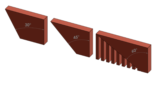
In 3D printing, structural supports are additional structures printed to hold and keep in place the parts of the model that overhang or lack adequate support during the printing process. These supports are essential for printing complex geometries and overhangs that would otherwise not be possible without deformation or failure.
Impact of Supports on the Final Result
Surface Quality:
- Finish: Supports can affect the surface finish of the object, as areas where supports are attached may require post-processing to remove marks or residue.
- Defects: Removing supports can leave marks or defects that need to be manually corrected.
Precision and Detail:
- Adequate Supports: Supports allow for the printing of fine details and complex features that would otherwise be difficult to achieve without deformation.
- Over-Supporting: Excessive support or poorly designed supports can affect the precision of the print and the alignment of parts.
Structural Strength:
- Stability: Supports help maintain the stability of the model during printing, reducing the risk of collapses or deformations due to gravity.
Recommended Overhang Angles in FDM and Existing Limits
Overhang Angles:
- Recommended: In FDM printing, an overhang angle of up to 45 degrees is generally considered acceptable without additional support. Overhangs exceeding this angle may require supports to avoid deformation.
- Limits: Overhangs greater than 60 degrees typically require supports to maintain the integrity of the model during printing, as the layers do not have enough surface to adhere properly.
Additional Considerations:
- Materials and Printing Settings: Different materials and printing settings allow for printing more pronounced overhangs without supports. Adjusting the print temperature, speed, and material flow can help improve the capability to print overhangs.
Base Support
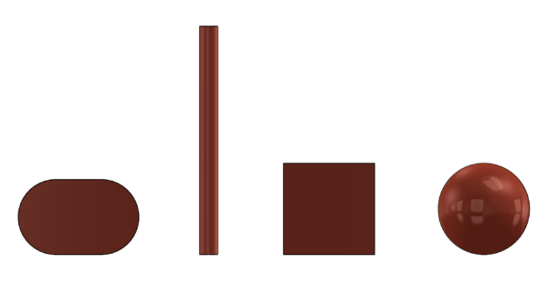
In 3D printing, base support and adhesion of a piece to the print bed are crucial to ensure that the object prints correctly without deformation or failure. Good adhesion ensures that the first layer of the model adheres firmly to the print bed, which in turn affects the overall quality and accuracy of the final object.
Impact of Base Support and Adhesion on the Final Result
Print Quality:
- Deformations: Inadequate adhesion can cause deformations or lifting of the model’s corners, affecting the geometry and precision of the final object.
- Shifts: Lack of proper base support can lead to issues such as warping (shrinkage and deformation) and layer separation.
Stability and Precision:
- Model Movement: A poorly adhered piece can shift during printing, resulting in a misaligned object or defects on the surface.
- Size and Shape: The dimensional accuracy of the object can be compromised if the base support is unstable during the printing process.
Optimal and Non-Optimal Geometric Shapes for Adhesion
Optimal Geometric Shapes:
- Flat and Wide Surfaces: Bases with flat and wide surfaces provide better adhesion to the print bed. This includes shapes such as cubes, prisms, and flat bases of models.
- Bases or Support Plates: Designing a wide base or a support plate under the model can enhance adhesion and stability, especially for models with a small contact area.
Non-Optimal Geometric Shapes:
- Small Points: Shapes with very small contact points, such as spikes or thin edges, have poorer adhesion and are more prone to detaching during printing.
- Sharp Angles: Areas with sharp angles or protruding shapes can be more challenging to adhere and may require additional support to maintain stability during printing.
Space between moving parts
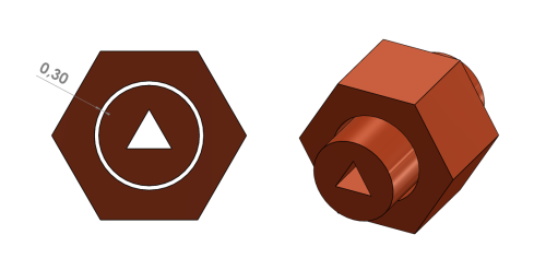
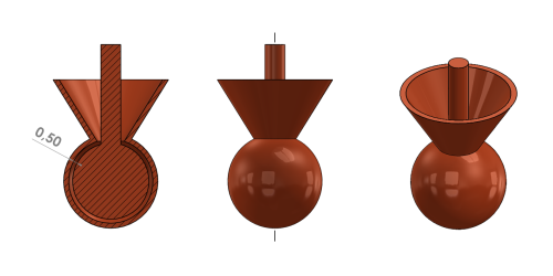
When printing 3D models with moving parts, it’s crucial to account for the correct spacing between components to ensure proper functionality and prevent mechanical issues. Proper spacing helps in achieving smooth movement, preventing jamming or binding, and ensuring the durability of the final product.
Impact of Spacing on the Final Result
Functionality:
- Smooth Movement: Adequate spacing ensures that moving parts can operate smoothly without friction or binding. This is essential for mechanisms and assemblies where parts need to move freely.
- Mechanical Reliability: Proper spacing helps prevent mechanical failures such as seizing or excessive wear, which can occur if parts are too tight or misaligned.
Accuracy and Fit:
- Precision: Incorrect spacing can lead to inaccuracies in the final dimensions and fit of the parts, affecting how well they assemble or function together.
- Play and Tolerance: Proper spacing also controls the amount of play or tolerance in the moving parts, impacting the precision and performance of the mechanism.
Geometric Shapes and Required Spacing
Cylindrical Shapes:
- Bearings and Shafts: For cylindrical parts like bearings and shafts, a typical spacing of 0.1 mm to 0.3 mm around the shaft diameter is recommended. This spacing allows for smooth rotation and prevents the parts from binding.
- Sleeves and Bushings: Ensure there is enough clearance between the inner surface of the sleeve and the outer surface of the shaft, considering both the material’s thermal expansion and the print resolution.
Spherical Shapes:
- Ball Joints and Sockets: For spherical components such as ball joints or sockets, a clearance of 0.2 mm to 0.5 mm is usually adequate. This spacing ensures that the ball can fit into the socket without excessive friction.
- Rudimentary Joints: For basic rotating or pivoting joints, a larger gap may be needed to account for slight inaccuracies in printing and thermal expansion.
Other Geometric Shapes:
- Interlocking Parts: For interlocking or sliding parts, such as gears or sliders, ensure a gap of at least 0.2 mm to 0.5 mm between moving surfaces to accommodate material shrinkage and printing imperfections.
- Hinges and Articulations: Hinges and articulated joints generally require a spacing of 0.3 mm to 0.6 mm to ensure they operate smoothly and without binding.
Assembly
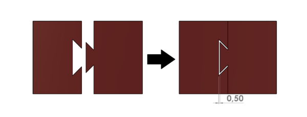
When printing parts that will be assembled together, it’s essential to account for the correct spacing between components to ensure that they fit together correctly and function as intended. Proper spacing is crucial for achieving accurate assembly, preventing misalignment, and ensuring the ease of assembly.
Impact of Spacing on the Final Result
Fit and Alignment:
- Assembly Ease: Proper spacing ensures that parts fit together accurately without excessive force or misalignment, which is essential for smooth assembly and function.
- Precision: Inaccurate spacing can lead to gaps or tight fits, affecting the overall performance and aesthetic of the assembled object.
Mechanical Functionality:
- Movement and Function: For parts that need to move or interlock, adequate spacing allows for proper movement and function, preventing jamming or mechanical failure.
- Tolerance: Proper spacing accommodates the tolerances of the 3D printing process and the material properties, ensuring that assembled parts work together as intended.
Geometric Shapes and Required Spacing
Cylindrical Shapes:
- Pins and Holes: For cylindrical parts such as pins and holes, a typical clearance of 0.1 mm to 0.3 mm around the pin diameter is recommended. This spacing ensures that pins fit smoothly into holes without binding.
- Cylindrical Shafts: When designing cylindrical shafts that fit into sleeves or bearings, ensure there is a gap of about 0.1 mm to 0.3 mm to account for material expansion and printing tolerances.
Wedges and Interlocking Parts:
- Wedges: When designing wedges or tapered parts that fit into each other, a clearance of 0.2 mm to 0.5 mm is usually sufficient. This gap accommodates minor inaccuracies in printing and prevents tight fits.
- Interlocking Parts: For interlocking components, such as puzzle pieces or gear teeth, ensure a spacing of about 0.2 mm to 0.5 mm between interlocking surfaces to allow for easy assembly and movement.
Triangular and Other Geometric Shapes:
- Triangular Joints: For triangular joints or fittings, a gap of 0.2 mm to 0.4 mm is recommended to ensure proper alignment and prevent binding.
- Complex Geometries: For complex geometric shapes, such as custom connectors or multi-part assemblies, the spacing needs to be adjusted based on the specific design and function of the parts.
Engraved and embossed details
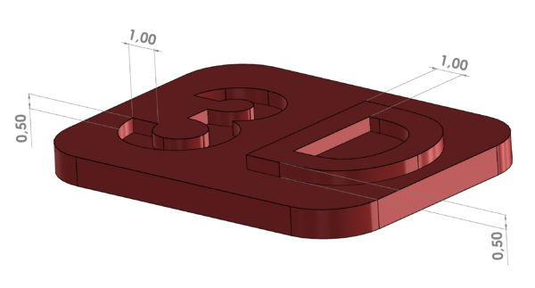
In 3D printing, engraved (recessed) and embossed (raised) details are crucial for adding texture and aesthetic features to models. Accuracy in the depth and width measurements of these details is fundamental to ensure they are visible and well-defined, and to avoid printing issues.
Impact of Measurements on the Final Result
Detail Clarity:
- Appropriate Depth and Width: Proper depth and width measurements ensure that engraved and embossed details are clearly represented and not lost during the printing process.
- Defined Details: Details with measurements that are too small can be difficult to print accurately, leading to blurry or inaccurate features.
Structure and Stability:
- Durability: Details that are too deep or narrow can weaken the structure of the model, making it more prone to breaking or damage.
- Adhesion and Stability: Very small or fine details may not adhere properly to the print bed, affecting the overall stability of the object.
Recommended Measurements for Engraved and Embossed Details
Engraved Details:
- Depth: For engraved details, the recommended minimum depth is typically at least 0.5 mm to 1 mm. Shallower depths may result in unclear details or details that do not print correctly.
- Width: The minimum width of engraved details should be at least 0.5 mm to prevent obstructions or loss of definition. Finer details may be problematic and require design adjustments.
Embossed Details:
- Height: Embossed details should have a minimum height of approximately 0.5 mm to 1 mm to ensure they are visible and do not collapse during printing. Heights smaller than this may not be robust enough.
- Width: The minimum width of embossed details should also be at least 0.5 mm. Narrower details may result in an inaccurate finish or difficulties during printing.
Threads
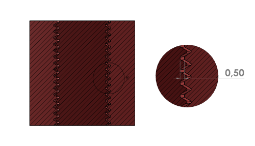
Internal and external threads are common features in 3D designs that require special precision to ensure a correct fit and functionality. Proper measurement of these threads is crucial for the assembly and use of printed parts.
Impact of Measurements on the Final Result
Fit and Functionality:
- Internal Threads: A diameter that is too small may prevent the screw or threaded piece from fitting properly, while a diameter that is too large may result in a loose fit.
- External Threads: An incorrect outer diameter may lead to a screw that does not fit well into the corresponding internal thread, affecting functionality and assembly.
Precision and Finish:
- Thread Definition: Incorrect measurements can lead to poor thread finishing, with possible imperfections or distortions that affect assembly.
- Printing Tolerances: Precision in thread dimensions affects the printer’s ability to reproduce fine details, influencing the fit and smoothness of the thread.
Recommended Measurements for Internal and External Threads
External Threads:
- Outer Diameter: For external threads, the diameter should be slightly larger than the nominal diameter of the screw. A good rule of thumb is to add a tolerance of approximately 0.2 mm to 0.5 mm to the nominal diameter.
- Thread Height: The height or depth of the external thread should be sufficient to ensure a good grip. Generally, a depth of 1.5 mm to 2 mm is suitable for many applications, but it may vary depending on the thread size.
Internal Threads:
- Inner Diameter: For internal threads, the diameter should be slightly smaller than the nominal diameter of the screw to allow for a proper fit. A tolerance of approximately 0.2 mm to 0.5 mm below the nominal diameter is recommended.
- Thread Depth: The depth of the internal thread should be sufficient to allow the screw to fully engage, with a recommended minimum depth of 1.5 mm to 2 mm. This ensures good contact between the threads and a firm fit.
Threaded Insert Fit
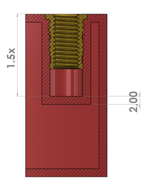
When incorporating threaded inserts into a 3D print, it is crucial to adjust the model’s wall measurements to ensure a precise and durable fit. Inadequate measurements can affect the functionality of the insert and the robustness of the final model.
Impact of Measurements on the Final Result
Insert Fit:
- Inner Diameter: The inner diameter of the hole where the threaded insert will be placed must be accurate to ensure the insert fits securely without play or being too tight. Incorrect fitting can lead to poor holding or difficulties during assembly.
- Hole Depth: The depth of the hole should be sufficient for the insert to sit completely flush without protruding. Insufficient depth can result in incomplete fitting or an insert that does not secure properly.
Structural Integrity:
- Wall Thickness: The surrounding walls of the hole must be thick enough to support the insert without weakening the model’s structure. Walls that are too thin may cause the part to break or deform under stress.
- Load Distribution: Ensuring that the walls are adequate to support the load and stress that the insert may apply is essential for the model’s durability.
Recommended Measurements for Threaded Insert Fit
Inner Diameter of the Hole:
- Tolerance: The diameter of the hole should be slightly larger than the outer diameter of the threaded insert to allow for a comfortable fit. A tolerance of approximately 0.2 mm to 0.5 mm is generally suitable. The precise tolerance may vary depending on the size and type of insert.
- Fit: Check the insert specifications to ensure that the hole diameter in the model is within the recommended range for a secure fit.
Hole Depth:
- Adequate Depth: The hole depth should be sufficient for the insert to be fully seated. The recommended minimum depth is typically at least 1.5 times the length of the insert to ensure a firm fit.
Wall Thickness:
- Recommended Thickness: The minimum thickness of the walls around the hole should be at least 1 mm to 2 mm to ensure model robustness. This thickness may vary depending on the size of the insert and the material used.
Optimal Materials for Threaded Inserts in FDM
Recommended Materials:
- PETG: This material is ideal for applications requiring strength and durability. Its good adhesion and flexibility make it suitable for models with threaded inserts.
- Nylon: Nylon offers excellent strength and flexibility, making it useful for parts that endure loads or stress. It is ideal for threaded inserts and can withstand wear.
- ABS: ABS is strong and resistant, making it suitable for structural applications. However, its tendency to warp may require controlled printing conditions.
Less Recommended Materials:
- PLA: Although easy to print and cost-effective, PLA may be less resistant to high temperatures and mechanical stress, which may not be ideal for applications requiring durable threaded inserts.
BULK 3D PRINTING
Guide to preparing bulk files
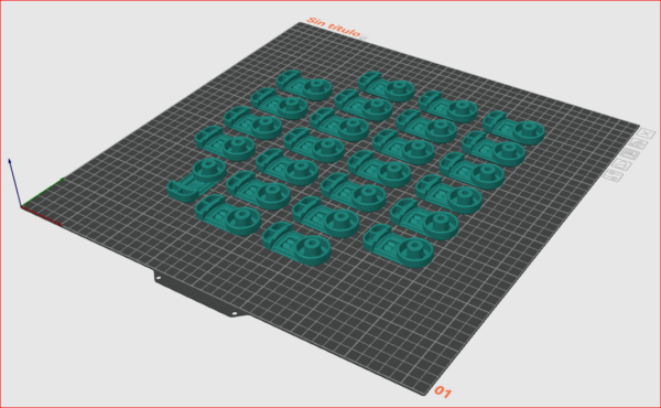
1. Download and Install OrcaSlicer
To maximize the use of your 3D printer’s workspace and send models in a single job, we recommend using OrcaSlicer.
Download OrcaSlicer:
- Visit the official OrcaSlicer website: OrcaSlicer Download
- Select the appropriate version for your operating system and download the installer.
Install OrcaSlicer:
- Run the downloaded file and follow the installation wizard instructions.
- Once installed, open OrcaSlicer.
2. Preparing .stl Files with OrcaSlicer
To group several models into a single print job and optimize the printing process:
Edit Build Size:
It will be necessary to change the size of the build space and adapt it to our case: 480 mm (Z height) x 420 mm (X width) x 420 mm (Y depth). To do this, follow these steps:
- Go to the “Printer” section.
- Click on “Click to change initial setting”.
- Change the “Printable height” to 480 mm.
- In the “Printable area” adjustment, leave the default rectangular shape.
- In the size settings, change both X and Y sizes to 420 mm.
- Click OK.
- Close the window.
Import Models:
- Go to the “Prepare” tab to open the workspace in OrcaSlicer.
- Drag the .stl file into the workspace to import it.
Organizing Models:
- Navigate to the “Auto-Orient” tab to adjust the orientation of the models.
- To duplicate a model, right-click on the object, select “Clone,” and choose the number of copies you want. Note: If you want 25 pieces in total and already have one in the workspace, select 24 as the number of copies to clone.
- After cloning the models, go to the “Arrange All Objects” tab to efficiently distribute them in the workspace. Then, click on “Organize”.
Export the File:
- Go to “File” > “Export” > “Export All Objects as a Single STL…” to save the prepared file.
